Overview
This article describes how to connect a +5V 8-Channel Relay Module by SainSmart to a Raspberry Pi 3 Model B+ using the SMD NPN Relay Module Interface Board by Same Day Rules. It also shows you how to configure and program the Raspberry Pi to control the SainSmart relay module.
We’re assuming that the Raspberry Pi is fully operational, and is running Raspberry Pi OS with Python 3 installed. We’re also assuming that we have access to a command line shell through some interface connected to the Raspberry Pi (e.g., PuTTY).
Parts Required
- Raspberry Pi 3 Model B+ (1 ea)
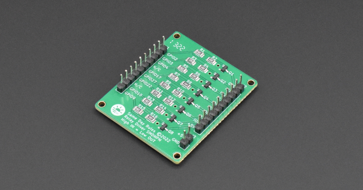
- Same Day Rules SMD NPN Relay Module Interface Board (1 ea)
- USB Type A power supply +5VDC @ 3A with USB Type A female receptacle (1 ea)
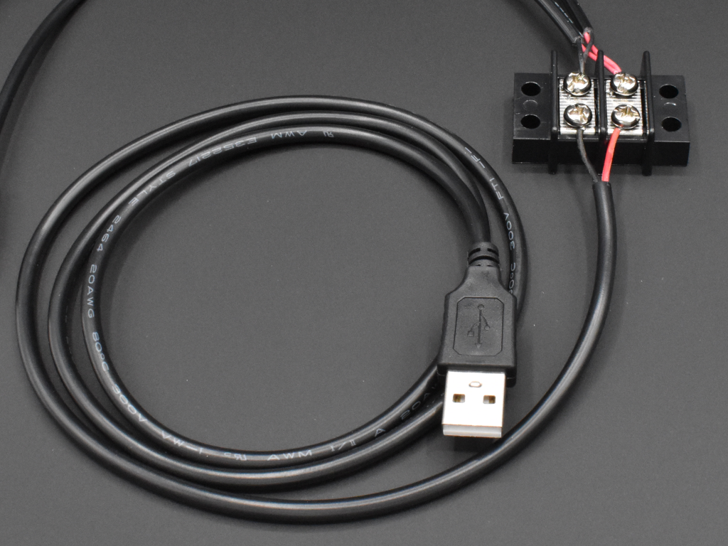
- USB Type A cable with USB Type A male plug on one end and bare power wires on the other (1 ea)
- Micro USB cable with micro USB male plug on one end and bare power wires on the other (1 ea)
- Two-conductor (20 AWG) hook-up wire (1 ft)
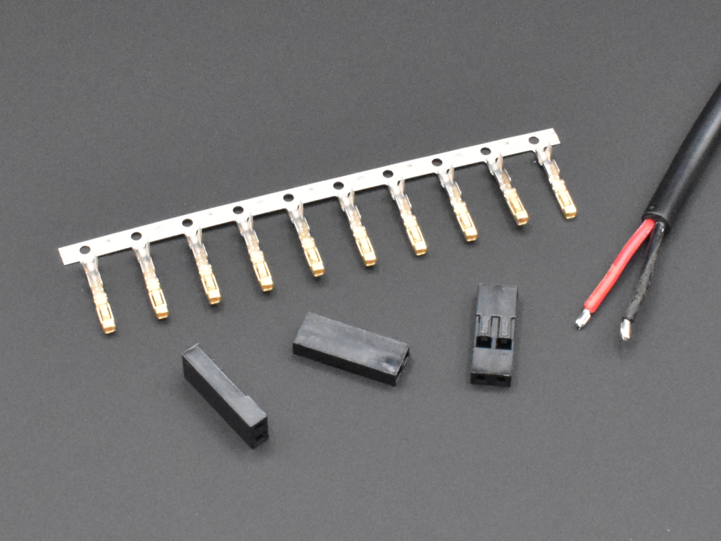
- Two-position 0.10 inch pitch cable-to-board receptacle with contacts (1 ea)
- Two-position dual-row terminal strip with #6 or #8 screws (1 ea)
- SainSmart 8-Channel 5V Relay Module (1 ea)
- Three inch Same Day Rules IDC Single-Row 10-Conductor Cable (2 ea)
- Multi–meter capable of measuring AC and DC voltages (1 ea)
Warning
Be careful attaching high voltages (AC or DC) to the relays; the relays have maximum ratings that should never be exceeded. You must be qualified to handle high-voltage and/or high-current devices and power supplies. You can be injured or killed or you can start a fire if proper precautions are not taken.
Approach
Our goal is to be able to control the relays on the SainSmart module using a Python script running on the Raspberry Pi. The relays act like switches, so you can control a large variety of devices that are activated by the throw of a switch (e.g., sprinkler valves, electronic locks, model rocket launchers).
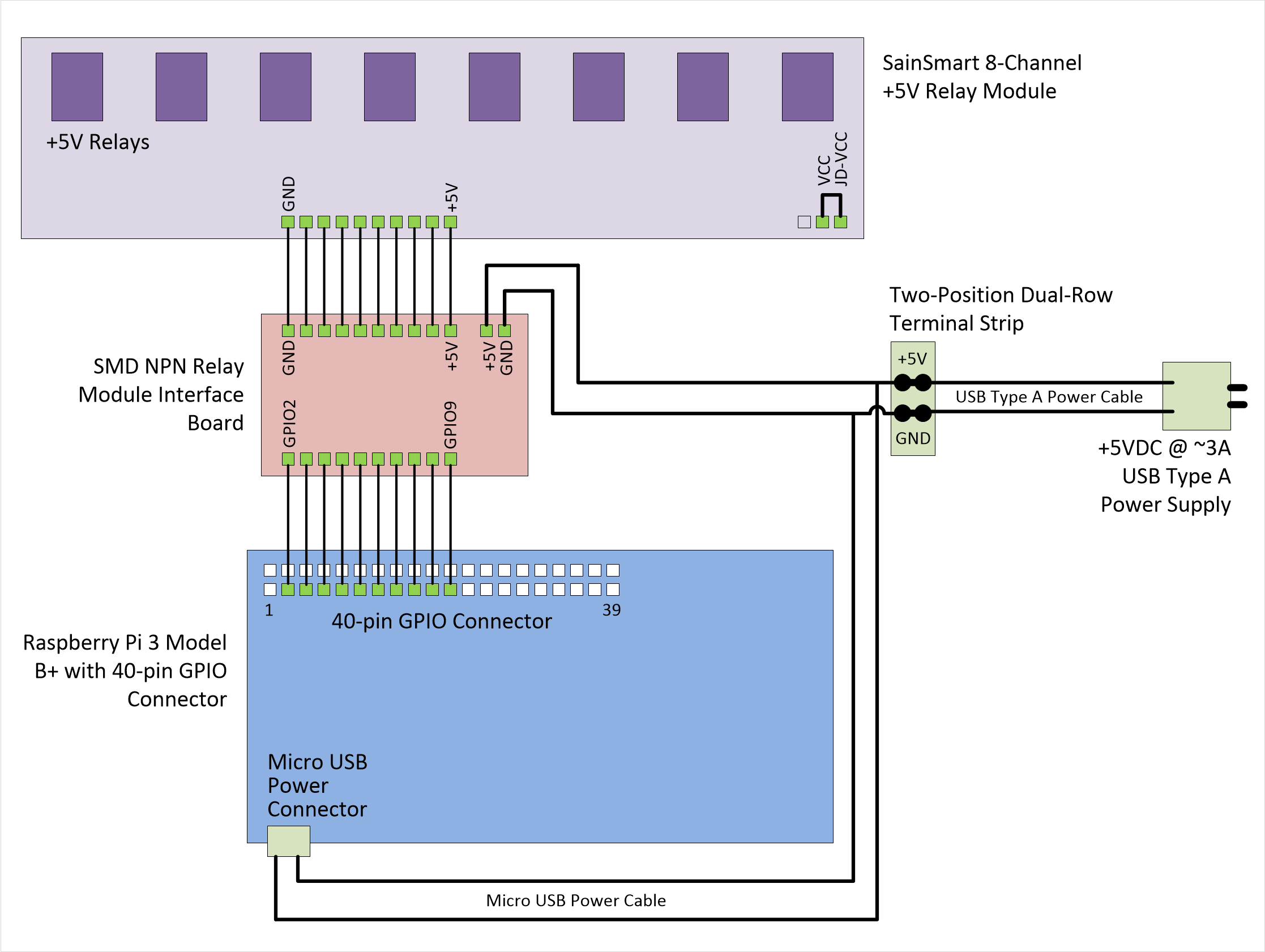
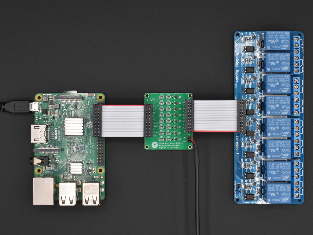
We’re going to power the Raspberry Pi and the SMD NPN Relay Module Interface Board from a single AC/DC wall adapter through a terminal strip. Then we’ll connect the Raspberry Pi to the SainSmart 8-Channel 5V Relay Module through the SMD NPN Relay Module Interface Board, which allows the 3V Raspberry Pi GPIO interface to safely connect to the 5V relay board.
Finally, we’ll use a Python script to control the relays. Below is a block diagram showing how all the components are connected.
Power
We’ll be using a single USB Type A power supply for the Raspberry Pi and the SMD NPN Relay Module Interface Board; this allows us to easily connect ground across the devices to ensure proper voltage levels on our control signals. For testing purposes, we can use a power supply that provides +5VDC @ ~3A; this will supply more than enough current for both the Raspberry Pi and our relay board even with all of the relays activated at the same time. We’re also using power supply cables that have 20-22 AWG wires; with very short cable runs at low power, we’ll be fine. On a fielded system, we would want to use a power supply that exceeds our maximum current requirements (which might be more than +5VDC @ 3A), and we would want to use wire sizes on the order of 18 AWG (see American Wire Gauge Current Ratings). Note that during testing, with all eight relays activated at the same time and the Raspberry Pi running the Python script, we measured a maximum current draw of only 800 mA @ +5VDC.
Power from the USB Type A Power Supply to the Terminal Strip:
Take the bare ends of the USB Type A power cable and screw them to the two posts on the two-position terminal strip; if you’re using the cable with the alligator clips, just secure the ends to the terminal strip screws. Take the other end of the cable and plug it into the USB Type A power supply. Get your multimeter ready and plug in the USB Type A power supply. Measure the voltage across the posts on the terminal strip, and verify that it reads +5VDC. Note which post is the positive (+) side of the power supply. Unplug the power supply.
Power from the Terminal Strip to the Raspberry Pi:
Take the bare ends of the micro USB cable and screw the wires to the two posts of the two-position terminal strip, opposite the wires that were attached to the terminal strip in the previous step. Make certain that you are connecting the positive (+) lead to the positive post on the terminal strip or you will likely damage the Raspberry Pi. The positive lead on the micro USB cable is usually the red wire. Plug the other end of the micro USB cable into the Raspberry Pi power connector.
Power from the Terminal Strip to the SMD NPN Relay Module Interface Board:
Strip both ends of the foot-long piece of two-conductor hook-up wire. Crimp contacts to both wires on one of the ends of the cable. Carefully insert the contacts into the two-position 0.10 inch pitch cable-to-board receptacle. Take the other end of the cable and screw the bare wires to the two posts of the two-position terminal strip on the same posts that you used in the previous step. Make certain that you are connecting the positive (+) lead to the positive post on the terminal strip or you will likely damage the relay module. The positive lead on this cable is whatever you decide it to be; just make sure you note which wire is the positive wire. Plug the other end of the cable into J3 of the SMD NPN Relay Module Interface board, again making certain that you are inserting the connector with the positive (+) wire connecting to the positive pin on J3 of the board (the positive pin is marked +5V).
Connections
Make sure that all power supplies are disconnected and turned OFF.
Connect Raspberry Pi GPIO pins 3-21 to J1 of the SMD NPN Relay Module Interface Board using one of the IDC Single-Row 10-Conductor Cables. This is a straight connection between the two boards. Raspberry Pi GPIO pinouts.
Connect J2 of the SMD NPN Relay Module Interface Board to J9 (the 10-pin input connector) of the SainSmart 8-Channel 5V Relay Module. This is a straight connection between the two boards. SainSmart 8-Channel 5V Relay Module schematic.
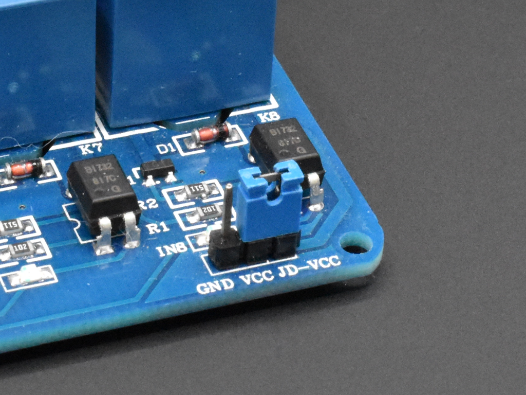
Place a two-position jumper on the three-position header of the SainSmart 8-Channel 5V Relay Module between the pins labeled VCC and JD-VCC; this routes power from J9 to each of the relays so that a single power supply can be used on the relay board.
Double-check the power connections going to and coming from the two-position terminal strip that attaches to the USB Type A power supply. Red-to-red, black-to-black, positive-to-positive, ground-to-ground.
Now plug in the USB Type A power supply. Check to make sure that the Raspberry Pi has powered on and is functioning nominally. One or more of the relays may activate as the signals coming from the Raspberry Pi GPIO interface haven’t been configured yet.
Configuring Raspberry Pi OS
Before we start programming, we want to modify the way the GPIO interface behaves when we boot the processor. Specifically, we want to configure the GPIO pins connected to the SMD NPN Relay Module Interface Board as outputs and drive them low so that we help avoid activating a relay prematurely before our Python script runs. There are several stages that the GPIO pins go through during the boot process, and controlling pin behavior can be relatively complex during the early stages. We’re going to jump in around the middle stage and tell the OS to set the GPIO pins of interest to a safe state. We do this by modifying an OS configuration file called config.txt. This file is normally accessible as /boot/config.txt from Linux, and must be edited as root. Log into the Raspberry Pi and follow these steps to change the config.txt file to setup the GPIO pins we’re using as output pins (op) with no pull-up/down (np) and driven low (dl):
$cd /boot
$sudo nano config.txt
Move to the end of the file, and add this line:
gpio=2,3,4,9,10,17,22,27=op,np,dl
Save the file and exit the editor. Reboot to load the changes.
$sudo reboot
Now during the boot process, fairly early, the GPIO pins that are controlling our relays will be put is a safe state. Note that in order to avoid any of the relays from being activated upon power-up or reboot, you’ll have to use GPIO pins that are initialized at the lowest levels of the interface as output pins set to a low signal level state. The datasheet on the BroadComm BCM2835 peripheral controller used by the Raspberry Pi 3 Model B+ under the section titled Alternative Function Assignments shows which pins are initialized in a low signal state.
Programming
We’re going to be using a fairly popular Python module called RPI.GPIO to control the SainSmart relay module. It’s not the only module available to control the GPIO pins, but it’s very easy to use. To activate a relay, all we have to do is make the pin connected to it go LOW (the SainSmart relay module is “active-low”). The logic of the SMD NPN Relay Module Interface Board is such that making an input pin on J1 of the board go HIGH, causes the corresponding output pin on J2 to go LOW, which turns ON the associated relay. This means making a GPIO pin on the Raspberry Pi go HIGH causes a relay on the SainSmart board to turn ON. Here’s the link to the RPi.GPIO module:
https://sourceforge.net/p/raspberry-gpio-python/wiki/BasicUsage/
Log into the Raspberry Pi and follow these steps to make a new Python script:
$pip install RPi.GPIO
$nano relays.py
Enter the following lines, then save the file, and exit the editor:
# Originally posted:
# https://samedayrules.com/using-smd-npn-relay-board

import RPi.GPIO as GPIO # access to GPIO pins
import time # use this to pause execution below

pins = [2, 3, 4, 17, 27, 22, 10, 9] # list of pins we'll be using
GPIO.setmode(GPIO.BCM) # reference pins using logical pin numbers
GPIO.setup(pins, GPIO.OUT) # set all pins to output mode
GPIO.output(pins, GPIO.LOW) # set all pins low (de-activates relays)

# Loop through pins, turning them ON, pausing, then OFF
for p in pins:
    GPIO.output(p, GPIO.HIGH) # relay associated with this pin should now be ON
    time.sleep(3) # pause for 3 seconds
    GPIO.output(p, GPIO.LOW) # relay should now be OFF

# Turn all the relays ON and then OFF
GPIO.output(pins, GPIO.HIGH)
time.sleep(3)
GPIO.output(pins, GPIO.LOW)

# Cleanup
GPIO.cleanup()
Execute the script:
$python relays.py
You may see warning messages coming from the RPi.GPIO module as you initialize the pins as outputs; this is usually because the module sees some other part of the Raspberry Pi OS as having access to the GPIO pins. This is normal, and you can turn off the warning messages through the RPi.GPIO module.
That’s it. You now have full control of the SainSmart relay module, and can modify the code above to suit your application. Remember that the power supply connected to the SMD NPN Relay Module Interface Board needs to be sized appropriately for your application, depending upon how many relays you want to activate at the same time.
You can find all of our code posted to this blog on the Same Day Rules GitHub page.