Overview
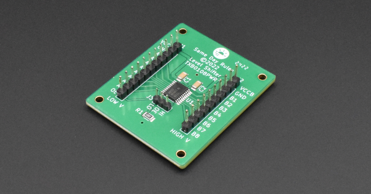
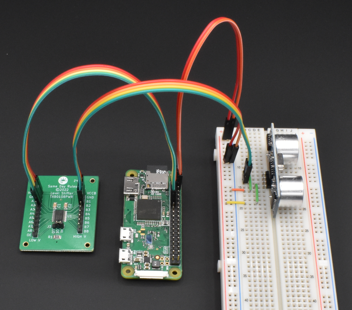
This article describes how to connect an HC-SR04 Distance Sensor by Smraza to a Raspberry Pi Zero W using the TXB0108PWR 8-Bit Level Shifter board by Same Day Rules. It also shows you how to configure and program the Raspberry Pi to control the HC-SR04 distance sensor.
The HC-SR04 operates at +5 volt signal levels while the Raspberry Pi input/output pins operate at +3.3V volt signal levels. The level shifter board allows the Raspberry Pi to safely interoperate with the distance sensor by shifting the +3.3V signals into the +5V range and vice versa.
We’re assuming that the Raspberry Pi is fully operational, and is running Raspberry Pi OS with Python 3 installed. We’re also assuming that we have access to a command line shell through some interface connected to the Raspberry Pi (e.g., PuTTY).
Parts Required
- Raspberry Pi Zero W (1 ea)
- Same Day Rules TXB0108PWR 8-Bit Level Shifter Board (1 ea)
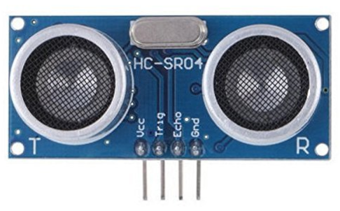
- HC-SR04 distance sensor (1 ea)
- Raspberry Pi 12.5W micro USB power supply (1 ea)
- Solderless breadboard with 0.10 inch pitch spacing for 22 AWG wire (1 ea)
- Jumper kit for 0.10 inch pitch pad spacing breadboards (1 ea)
- Two-conductor (multi-color ribbon) breadboard jumper cable (~6 inch) male/female (1 ea)
- Four-conductor (multi-color ribbon) breadboard jumper cable (~6 inch) male/female (1 ea)
- Four-conductor (multi-color ribbon) breadboard jumper cable (~6 inch) female/female (1 ea)
- Multi–meter capable of measuring AC and DC voltages (1 ea)
Approach
Our goal is to be able to control the HC-SR04 distance sensor using a Python script running on the Raspberry Pi microcomputer. The distance sensor is a time-of-flight acoustic ranging sensor operating at a frequency of 40 KHz (just beyond normal human hearing). See the technical specifications for the sensor. The sensor generates a sound wave that hits an object and bounces back to it; the time that it takes for the sound wave to travel out to the object and then back to the sensor is used to determine the range to the object.
We’re going to power the Raspberry Pi, the TXB0108PWR level shifter board, and the HC-SR04 distance sensor using the standard Raspberry Pi 12.5W micro USB power supply; it provides plenty of current for all three boards.
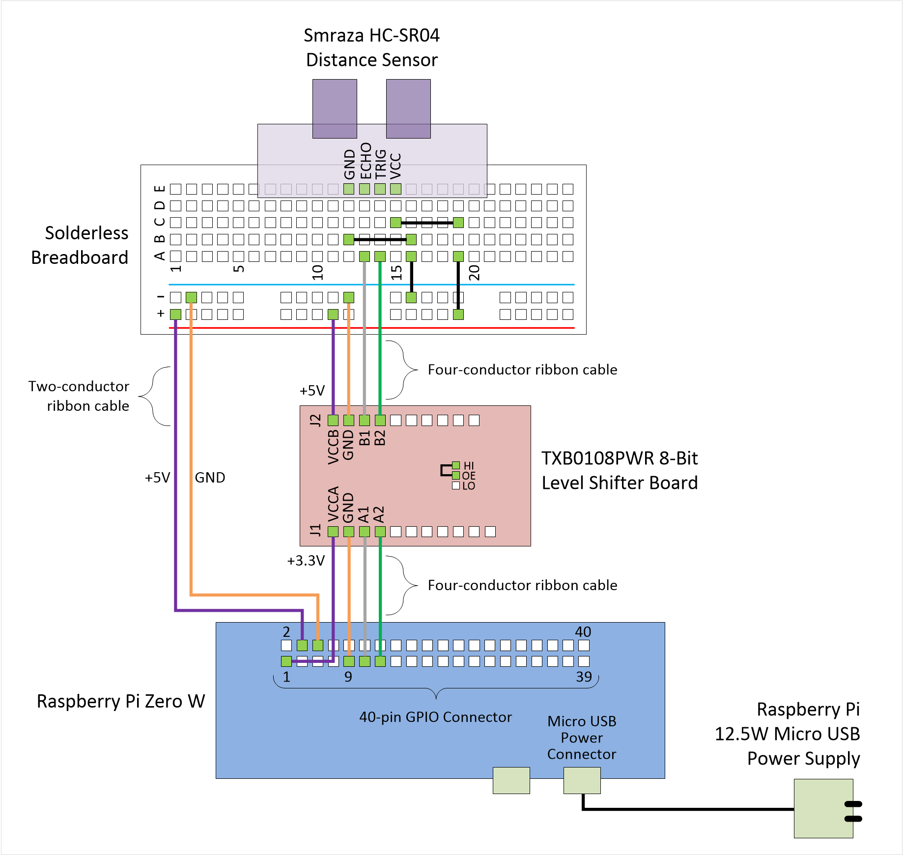
We’ll connect the Raspberry Pi to one side of the level shifter board and the distance sensor to the other side of the level shifter board. We’ll mount the distance sensor to our breadboard for ease of integration.
Finally, we’ll use a Python script to control the distance sensor to measure the range to obstacles in front of it. Below is a block diagram showing how all the components are connected.
Power
BE CAREFUL: If you accidentally connect positive voltage to negative voltage, you will do damage to the attached equipment. Double-check all of your power connections BEFORE you plug in the USB power supply.
READ ME: If you’re not skilled at using solderless breadboards for prototyping, then please read this excellent article by SparkFun titled How to Use a Breadboard.
We’ll be using a single +5V power supply that will plug into the Raspberry Pi, and then we’ll tap off of the +3.3V and +5V supply pins on the Raspberry Pi’s GPIO header to power the remaining two boards. We’re using power supply cables that have 20-22 AWG wires with very short cable runs, so supply current and voltage line drop will not be issues.
Power to the Raspberry Pi:
Attach the micro USB male plug of the USB power supply to the power connector on the Raspberry Pi; don’t plug the power supply into the wall just yet.
Power to the Breadboard:
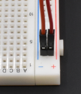
Using the two-conductor (multi-color ribbon) breadboard jumper cable male/female, plug the female end into pin 4 and pin 6 of the Raspberry Pi GPIO connector. Pin 4 is +5V and pin 6 is GND.
Next, plug the male end of the cable attached to pin 4 on the Raspberry Pi into the positive (+) rail on the breadboard, and plug the male end of the cable attached to pin 6 on the Raspberry Pi into the negative (-) rail on the breadboard. The positive rail should be adjacent to the red line on the breadboard and is marked with a plus sign, while the negative rail should be adjacent to the blue (or black) line on the breadboard and is marked with a minus sign.
Get your multimeter ready and plug in the USB power supply. Measure the voltage across the wires on the two-conductor ribbon cable where the cable is connected to the breadboard (you can insert your meter probes into the header where the pins are exposed). You should read approximately +5VDC. Shutdown the Raspberry Pi. Unplug the power supply.
Connections
Make sure that all power supplies are disconnected and turned OFF.
See the Raspberry Pi GPIO pinouts for details on the GPIO connector.
Using the four-conductor (multi-color ribbon) breadboard jumper cable female/female, plug one end into J1 of the TXB0108PWR level shifter board, and then connect the other end of the cable into the Raspberry Pi Zero W as follows:
| Raspberry Pi GPIO Pin # | TXB0108PWR J1 Pin # | Function: Raspberry Pi / TXB0108PWR |
|---|---|---|
| 1 | 1 | +3.3V / VCCA |
| 9 | 2 | GND / GND |
| 11 | 3 | GPIO 17 / A1 |
| 13 | 4 | GPIO 27 / A2 |
Using the four-conductor (multi-color ribbon) breadboard jumper cable male/female, plug the female end into J2 of the TXB0108PWR level shifter board, and then connect the other end of the cable into the breadboard as follows:
| Breadboard Pad # | TXB0108PWR J2 Pin # | Function: Breadboard / TXB0108PWR |
|---|---|---|
| Positive (+) power rail | 1 | +5V / VCCB |
| Negative (-) power rail | 2 | GND / GND |
| A13 | 3 | HC-SR04 ECHO / B1 |
| A14 | 4 | HC-SR04 TRIG / B2 |
Using the solid wire jumpers from the kit, make connections between the following pads on the breadboard:
| Breadboard Pad # (from) | Breadboard Pad # (to) | Function |
|---|---|---|
| B12 | B16 | GND for HC-SR04 |
| C15 | C19 | +5V for HC-SR04 |
| Negative (-) power rail | A16 | GND for HC-SR04 |
| Positive (+) power rail | A20 | +5V for HC-SR04 |
Next, insert the HC-SR04 distance sensor into the breadboard with the four pins inserted as follows:
| Breadboard Pad # | HC-SR04 Pin Name | Function |
|---|---|---|
| E12 | Gnd | GND |
| E13 | Echo | Echo (pulse width is proportional to distance) |
| E14 | Trig | Trigger (initiate pulse) |
| E15 | Vcc | +5V |
Finally, place a 2mm jumper across pins 2-3 (OE-HI) on the TXB0108PWR level shifter board; this causes the level shifter board to be enabled on power-up. The board will not function if the jumper is not installed.
Power Up
Now plug in the USB power supply. Check to make sure that the Raspberry Pi has powered on and is functioning nominally.
Configuring Raspberry Pi OS
Before we start programming, we want to modify the way the GPIO interface behaves when we boot the processor. Specifically, we want to configure the GPIO pins connected to the TXB0101PWR level shifter to operate as input/output pins by default. This isn’t strictly necessary, but it’s good practice to ensure, as best as possible, that the GPIO pins behave properly at startup.
There are several stages that the GPIO pins go through during the boot process, and controlling pin behavior can be relatively complex during the early stages. We’re going to jump in around the middle stage and tell the OS to set the GPIO pins of interest to a safe state. We do this by modifying an OS configuration file called config.txt. This file is normally accessible as /boot/config.txt from Linux, and must be edited as root. Log into the Raspberry Pi and follow these steps to change the config.txt file to setup the GPIO pins we’re using as follows:
- Physical pin 11 / logical pin GPIO 17 as an input (ip)
- Physical pin 13 / logical pin GPIO 27 as an output (op) with no pull-up/down (np) and driven low (dl)
$cd /boot
$sudo nano config.txt
Move to the end of the file, and add these two lines:
gpio=17=ip
gpio=27=op,np,dl
Save the file and exit the editor. Reboot to load the changes.
$sudo reboot
Programming
We’re going to be using a fairly popular Python module called RPI.GPIO to control the HC-SR04 distance sensor. It’s not the only module available to control the GPIO pins, but it’s very easy to use. To activate the HC-SR04, all we have to do is make the TRIGGER output pin go HIGH for a very short period, and then time the incoming (HIGH) signal on the ECHO input pin. Here’s the link to the RPi.GPIO module:
https://sourceforge.net/p/raspberry-gpio-python/wiki/BasicUsage/
Log into the Raspberry Pi and follow these steps to make a new Python script:
$pip install RPi.GPIO
$nano distance.py
Enter the following lines, then save the file, and exit the editor:
# Originally posted:
# https://samedayrules.com/using-the-voltage-level-shifter-board/

# Libraries
import RPi.GPIO as GPIO
import time

# GPIO mode (BCM = use logical pin numbers, e.g., GPIO 2 (I2C1 SDA))
GPIO.setmode(GPIO.BCM)

# Set GPIO pins
GPIO_TRIGGER = 27 # make this go HIGH for at least 10us to initiate pulse
GPIO_ECHO = 17    # the amount of time this goes HIGH represents distance

# Set GPIO direction (IN / OUT)
GPIO.setup(GPIO_TRIGGER, GPIO.OUT)
GPIO.setup(GPIO_ECHO, GPIO.IN)

# Make sure trigger starts LOW
GPIO.output(GPIO_TRIGGER, GPIO.LOW)

# Timeouts used to stop wait loops below in case of hardware failure
TIMEOUT_RISING_EDGE = 1.5  # seconds to wait for ECHO rising edge
TIMEOUT_FALLING_EDGE = 2.0 # second to wait for ECHO falling edge

# Initiate sensor pulse, read pulse width, and return distance in cm
def distance():
    # Calculate timeouts for how long to wait for rising/falling edge of echo
    # Set trigger to HIGH, wait for 10us, then set trigger to LOW
    # Save the start time
    # Wait for echo to go HIGH
    # Save the stop time
    rising_timeout = time.perf_counter() + TIMEOUT_RISING_EDGE
    falling_timeout = time.perf_counter() + TIMEOUT_FALLING_EDGE
    GPIO.output(GPIO_TRIGGER, GPIO.HIGH)
    time.sleep(0.00001)
    GPIO.output(GPIO_TRIGGER, GPIO.LOW)
    while GPIO.input(GPIO_ECHO) == GPIO.LOW:
        if time.perf_counter() > rising_timeout:
            return 0.0
    start_time = time.perf_counter()
    while GPIO.input(GPIO_ECHO) == GPIO.HIGH:
        if time.perf_counter() > falling_timeout:
            return 0.0
    stop_time = time.perf_counter()

    # Calculate time difference between start and stop
    delta_T = stop_time - start_time

    # Speed of sound is nominally 34,300 cm/s
    # Multiply by the speed of sound/2 = 34300/2 = 17150.0
    # We divide by two because we're timing the round trip (there-back)
    d = delta_T * 17150.0

    return d

if __name__ == '__main__':
    try:
        while True:
            # Measure the distance, print its value, and wait for a bit
            dist = distance()
            # Sensor range is from 2 cm to 400 cm - flag anything out of range
            if dist > 2.0 and dist < 400.0:
              print("Range: %.1f cm / %.1f in" % (dist, dist/2.54))
            else:
              print("Range: invalid")
            time.sleep(1)

        # Reset by pressing CTRL + C
    except KeyboardInterrupt:
        print("\nTerminated by user")
        GPIO.cleanup()
The constants TIMEOUT_RISING_EDGE and TIMEOUT_FALLING_EDGE are guards against the while loops inside the distance() function from never exiting; if the hardware fails, then we may never see the ECHO line fall (go LOW) or rise (go HIGH) and the loops would otherwise never exit.
Execute the script:
$python distance.py
Range: 217.3 cm / 85.5 in
Range: 218.6 cm / 86.1 in
Range: 218.0 cm / 85.8 in
Range: 25.9 cm / 10.2 in
Range: 27.7 cm / 10.9 in
Range: 27.4 cm / 10.8 in
Range: 21.7 cm / 8.5 in
Range: 16.5 cm / 6.5 in
Range: 26.8 cm / 10.5 in
Range: 35.4 cm / 13.9 in
Range: 40.7 cm / 16.0 in
Range: 36.2 cm / 14.3 in
Range: 27.7 cm / 10.9 in
Range: 35.3 cm / 13.9 in
Range: 41.8 cm / 16.5 in
Range: 30.4 cm / 12.0 in
Range: 218.2 cm / 85.9 in
Initially, you may see warning messages coming from the RPi.GPIO module as you initialize the pins as outputs; this is usually because the module sees some other part of the Raspberry Pi OS as having access to the GPIO pins. This is normal, and you can turn off the warning messages through the RPi.GPIO module.
The program should begin to print range messages, once every two seconds. Occasionally, the range sensor provides an erroneous reading, reporting a distance measurement outside its operational range. Invalid range data is discarded, and an error message is displayed.
You can find all of our code posted to this blog on the Same Day Rules GitHub page.
TXB0108PWR Performance
From the TXB0108PWR datasheet, when VCCA is +3.3V and VCCB is +5V, then the data rate at which the device can operate is 100Mbps, with a maximum switching delay of approximately 4ns. The delay is important when timing the ECHO signal from the HC-SR04 as the distance to an object is proportional to the width of the ECHO pulse. However, since the delay is bounded to a maximum of 4ns, and the delay is likely to be fairly constant at a given fixed voltage level on VCCA and VCCB, the impact to the distance measurement should be negligible.
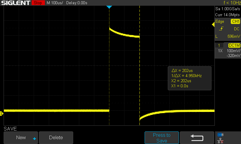
Below is an oscilloscope trace captured during the operation of the Python program above. The image shows the TRIGGER signal output from the TXB0108PWR (J2) after being sent by the Raspberry Pi to the TXB0108PWR (J1). Even though the Python time.sleep() function above was called with a duration of 0.01ms (10us), the resulting pulse duration is ~202us. This is likely due to the speed at which the Raspberry Pi Zero W is able to process the Python commands and the actual resolution of the time.sleep() function given the processor clock speed. The length of the TRIGGER signal is acceptable given that the pulse must be at least 10us.
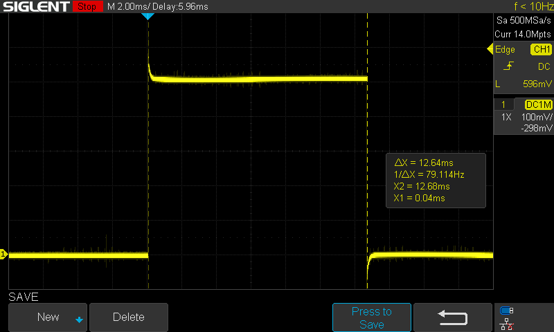
The image below shows the resulting ECHO signal output from the HC-SR04 that is sent through the TXB0108PWR to the Raspberry Pi. The pulse width is 12.64ms, which equates to a a distance of ~216.78cm. The ECHO signal as measured by the LOW/HIGH/LOW transition on the GPIO pin by the Python program running on the Raspberry Pi was 12.6409ms, which equates to a distance of ~216.79cm, which is satisfactory given the precision of the time value displayed on the oscilloscope.
The TXB0108PWR is a very flexible device that can be used in applications such as sensor interfacing. It is also very well suited as a data bus between digital systems operating at different voltage levels.